Intellivision Composite Video Modification
This modification was put together by Tim Lindner and Joe Zbiciak.
Overview
The Intellivision directly generates composite video using the AY-3-8915 Color Processor and a set of resistors. This video gets fed to the ASTEC UM1285-8 video modulator for conversion to RF for display on a television set. It is possible to tap this composite video directly to avoid the distortion and static associated with RF modulation and demodulation. On older units, the RF modulator can decay rather noticeably, leading to very low quality video.
Typical composite video inputs have an input impedance of 75Ω. In contrast, the composite signal generated by the Intellivision has a very high output impedance. (We estimate the output impedance is around 2KΩ.) Tapping this output and feeding it directly into a typical composite monitor does not work. (It will work if your monitor has a "high impedance" input, but such monitors are atypical.) Thus, an amplifier/impedance matching circuit is necessary. This Wikipedia article does a decent job of explaining the situation in general terms.
It is also possible to tap the audio the Intellivision generates. The audio output by the Intellivision is nearly directly suitable for feeding line-level inputs on most AV equipment. All that's required is a coupling capacitor.
The modification below should work equally well on all Intellivision variants, including the Intellivision 1, Intellivision 2, the various rebranded units (Sears, Tandy), and the later INTV releases.
Parts list
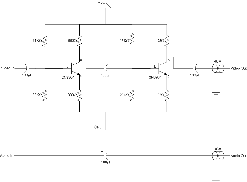
For the resistors, you can also achieve the necessary values by placing other resistors in series or parallel. For instance, you could use two 150Ω resistors in parallel in place of the 75Ω resistor. Or, you could use two 330Ω resistors in series in place of the 660Ω resistor. In general, you can often substitute nearby values for most of the resistors. If you're unsure of a given substitution, try it on a breadboard first. For the capacitors, it may be possible to go with much, much smaller values and still have good (perhaps better!) results. SPICE analysis suggests you may be able to go as low as or lower than 4.7µF for these capacitors. With 100µF capacitors, the circuit's bandwidth is approximately 16Hz to 5MHz. With 4.7µF capacitors, that becomes 330Hz to 5MHz. If you decide to try smaller values, you are encouraged to experiment on a breadboard and post your results. Values that are too small will lead to a display that looks darker on one side than the other. For the RCA connectors, you have two options: You can use board-mounted female connectors, or you can use connectors that are already part of a molded cable assembly. In the latter case, you can take a female-to-female shielded RCA cable, cut it in half, and have two connectors at your disposal. If you use this latter technique, use 75Ω video cable for best results. |
|
Schematic
Take careful note of the polarization for the capacitors. The 100µF capacitors have a positive and a negative lead. On typical dark-blue capacitors, the package indicates the negative lead with a light blue stripe along the side that points to the negative lead, usually with dashes in the stripe. Alternately, if the package is light blue, it will have a dark blue stripe indicating the negative terminal. In general, a stripe will indicate the negative lead.
Construction
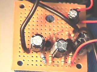
Build your circuit on the perf board as illustrated in the schematic above. Be sure to keep leads as short as possible to minimize noise. Remember, we're dealing with radio frequencies here. For the RCA connectors, connect the output signals to the center lead, and connect the shielding portion of the RCA connectors to ground. The directions below describe how to connect the perf board to the Intellivision.
Disassemble your Intellivision. For Intellivision 1 and related units, you will need to desolder the metal shield that surrounds the logic board. For the Intellivision 2, removing the top cover will suffice.
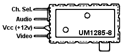
Locate the UM1285-8 RF Modulator. This is the metal box that provides the RF output from the Intellivision. The image below illustrates the modulator and the connections to it.
Depending on your preference, you can make your audio and video connections directly to the leads entering the RF modulator, or follow circuit traces to other convenient locations for you to connect to. Use the pinout detail above to guide your work.
For the video connection, connect (solder) the center wire of the shielded coax cable to the video line. Connect the shielding portion of the coax to a convenient grounding point on the Intellivision's logic board, or solder it to the metal can of the RF modulator. If soldering it to the modulator, be sure to clean the solder point first.
For the audio connection, connect ordinary hookup wire to the audio line.
For the +5v and ground, you have a couple options:
- For all systems, you can add a 7805 voltage regulator, tapping +12v at the RF Modulator to drive the 7805. This may be the most convenient, but it adds another component.
- For Intellivision 1 and related systems, the cleanest option is to tap directly off the main power supply board. Pin #1 on the power supply board's output provides +5v. Pin #4 provides GND. You can tap these either near the connector, or at convenient points elsewhere on the board.
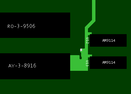
- For the Intellivision 2, you can tap GND at any of the many open pad points around the boundary of the motherboard. For +5v, one handy location is near U12/U13. The figure below shows the +5v trace of interest. (Note that the AY-3-8916 may instead be an AY-3-8914. The two AM9114s may instead be two 2114s.)
Troubleshooting
To aid troubleshooting, here are some reference voltages as measured in a working copy of the circuit. (Note: In this particular circuit, the 51kΩ resistor was replaced with a 50kΩ resistor, the 660Ω resistor was replaced with a 680Ω resistor and the 22kΩ resistor was replaced with a 21kΩ resistor. This is well within the circuit's tolerances but may shift the voltages slightly.)
- Q1 (left transistor in schematic)
- Collector: 3.2v
- Base: 1.5v
- Emitter: 0.85v
- Q2 (right transistor in schematic)
- Collector: 2.4v
- Base: 1.5v
- Emitter: 0.77v
Some have reported artifacts associated with this modification that can be overcome with slight tweaks.
- Smearing of bright areas: Add a large capacitor between +5v and GND on the board. FABombjoy on the AtariAge forums suggests 2000µF.
- Color shift near top of image: The root cause of this is unknown and is not seen on all systems. FABombjoy has had success with replacing the 22Ω resistor with a potentiometer and tweaking to a higher value. Values around 50Ω - 60Ω alleviate this problem.
Please contact Joe Zbiciak if you run into other issues with this circuit.


